The pneumatic conveying system is a set of equipment that uses the energy of airflow to convey powder and granular materials along the airflow direction in a closed pipeline. It is a specific application of fluidization technology. The pneumatic conveying system utilizes a specific feeding device to quantitatively deliver the conveyed material into the pipeline and employs positive and negative pressure gases (air, nitrogen, carbon dioxide, or methyl chloride, etc.) to transport the material to the designated location. It ensures that all conveying equipment and instruments operate automatically, orderly, and safely through the control system.
Composition of the Pneumatic Conveying System
The pneumatic conveying system mainly includes the following parts:
1. Power System: Mainly composed of an air compressor, dryer, air storage tank, etc. This is the power source of the entire conveying system.
2. Feeding System: Realized through a sending tank, rotary valve, spiral feeder, and other devices used for material reception and transportation.
3. Control System: Utilizes a microprocessor-based programmable controller, allowing for local manual control, automatic control, or remote centralized control.
4. Pipeline System: Mainly includes pipes of different diameters, elbows, and air supply valves to ensure the closed and stable transportation of materials.
5. Material Receiving and Auxiliary System: Includes a receiving tank, material level meter, dust collector, air release valve, discharge valve, etc. They are used to receive materials transported by the pipeline.
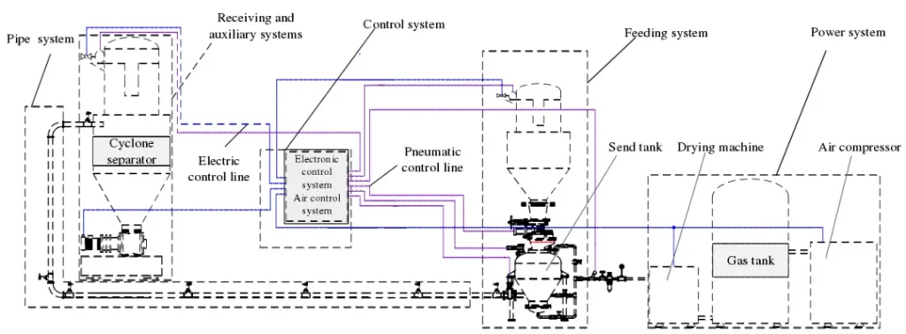
The feeding system is the key component of the pneumatic conveying system. The sending tank, also called a volumetric feeder or silo pump, has the advantages of sufficient material fluidization and controllable conveying speed. The rotary valve features a simple structure, convenient maintenance, small footprint, and low cost, making it widely used in pneumatic conveying systems. The spiral feeding device is a feeding mechanism that integrates the benefits of continuous feeding, adjustable flow, and speed.
Improvement Plan for Pneumatic Conveying in the Field of Fine Chemicals
Fine chemicals encompass new materials, functional materials, pharmaceuticals and pharmaceutical intermediates, pesticides and pesticide intermediates, food additives, beverage additives, flavors and fragrances, pigments and dyes, cosmetics, and daily chemicals. These materials have higher requirements for the reliability and metering accuracy of the conveying system.
The dense-phase pneumatic conveying system offers advantages such as high conveying efficiency, low energy consumption, and reduced pipeline wear. Based on the production characteristics of the fine chemical industry, the sending tank is generally selected for dense-phase pneumatic conveying.
For powdery materials with poor fluidity, the design of flow-aiding accessories and gas distribution components of the sending tank can be optimized. Effective anti-blocking measures can be implemented for the conveying pipeline, and production automation can be achieved through the automatic control system to meet the process requirements of solid material processing. Regarding the improvement of the conveying solution, Han Ruipuze shared a new type of dense-phase conveying equipment: a sending tank with a spherical mixer.
The new dense-phase sending tank assembly primarily consists of the sending tank body, spherical mixer, airflow control unit ACU-1 and ACU-2, weighing module, and other components.
Sending Tank Assembly with Spherical Mixer
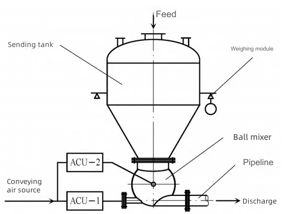
The ball mixer is the core component of the sending tank assembly. It is installed at the bottom outlet of the sending tank. It is specifically developed for powders with poor fluidity and metering process requirements. It plays a crucial role in temporarily storing and fluidizing materials, ensuring the safety and reliability of transportation while preventing residue, thus meeting the system’s metering accuracy requirements.
Schematic Diagram of the Ball Mixer Structure
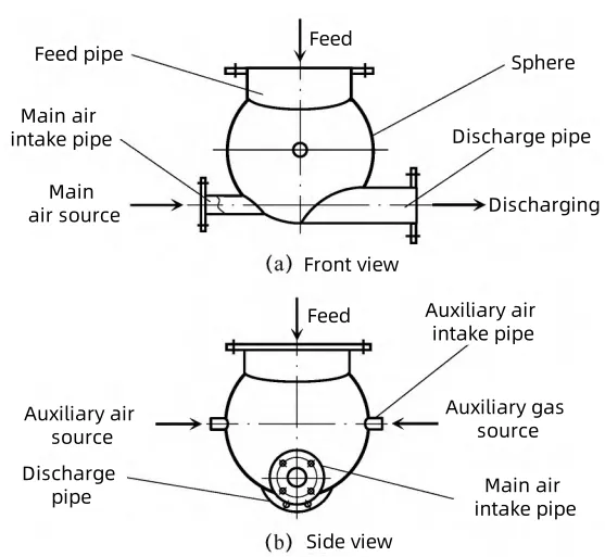
In the field of fine chemicals, the metering and conveying scheme is selected based on specific situations. The sending tank components and pneumatic conveying design are optimized, as illustrated in the optimized raw material metering and conveying process flow.
Schematic Diagram of the Raw Material Metering and Conveying Process Flow
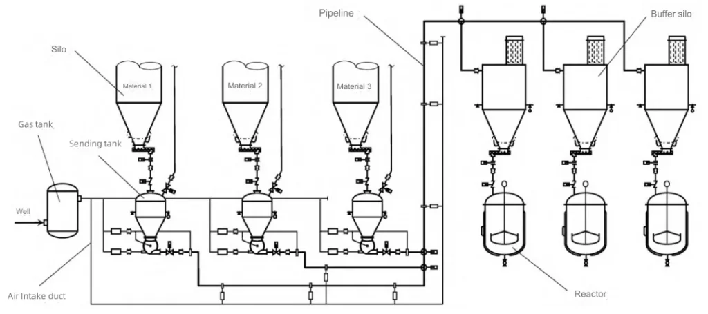
The outlets of material silos 1, 2, and 3 are equipped with variable frequency screw conveyors feeding. Each is paired with a sending tank that includes a weighing system. Each material is weighed and mixed according to formula requirements, achieving a metering accuracy of 0.5%. The mixture is sent to the pneumatic conveying pipeline. Then it’s transported to the buffer silo above the reactor in the production workshop. While the three materials share one pneumatic conveying pipeline, they are not transported simultaneously. Material 3 is conveyed first, followed by materials 1 and 2. The conveying capacity is 2t/h, the maximum conveying distance is 150m, and there are approximately 8 elbows.
The conveying gas source uses compressed air. To ensure the stability of the conveying gas source, a compressed air storage tank is installed near the sending tank.
In the production workshop, there are three reactors, each with a buffer silo that has a full volume of 5m³. Each buffer silo is equipped with a silo-top dust collector, a breathing valve, a 3-point weighing module, and a set of air disc flow aids at the cone. The three materials of each batch enter the same buffer silo. After batching each material, they are discharged into the corresponding reactor at once through the screw conveyor under the buffer silo. The maximum conveying capacity of the screw conveyor is 2t/h, and the conveying speed is adjustable.
Based on application examples, the dense-phase sending tank device utilizing a new spherical mixer. It can provide a solution for the fine chemical industry to process special materials. This also upgrades production technology, significantly improving production efficiency, automation levels, and environmental protection outcomes for enterprises.

